

Objective 2.3 – Configure and Manage Routing
- Deploy the appropriate NSX Edge (ESG/LDR) device according to a deployment plan
- Configure centralized and distributed routing
- Configure default gateway parameters
- Configure static routes
- Select and configure appropriate dynamic routing protocol according to a deployment plan:
- OSPF
- BGP
- IS-IS
- Configure route redistribution to support a multi-protocol environment
Deploy the appropriate NSX Edge (ESG/LDR) device according to a deployment plan
The distributed logical router (DLR) is a kernel module that allows the hypervisor to make routing decisions locally. It can perform routing between VXLAN networks and between virtual and physical networks. The DLR connects directly to logical switches. In doing so, it becomes the default gateway for virtual machines that are connected to logical switches. The DLR has support for static routes, BGP, and OSPF. By means of a DLR control VM, the DLR is able to make routing adjacencies with other network devices. The DLR is optimized for east-west data traffic. The DLR can have a total of 1000 uplink and internal interfaces
The NSX Edge services gateway provides common gateway services, such as DHCP, VPN, NAT, dynamic routing, and load balancing. The NSX Edge services gateway can be leveraged for North-South routing for connecting your virtual environment to the intranet/Internet. The NSX Edge provides centralized routing and is deployed as a virtual machine. The NSX Edge supports OSPF, BGP, Static Routes and Route Redistribution. Unlike the DLR, the Edge can support both OSPF and BGP together. The NSX Edge appliance can have a total of 10 uplink and internal interfaces.
Deploy a NSX Logical Distributed Router
Navigate to Networking & Security > NSX Edges and click the green +.

Click Logical Router to deploy a LDR. Enter in a name for the LDR. The Deploy Edge box is checked by default. Note: If you plan to do dynamic routing or use the logical router’s firewall, then a edge appliance is required. If you will only be using static routes, then there’s no need to deploy the appliance. You cannot deploy the edge appliance to the logical router after the logical router has been created.
Click Next.

Enter in a password for the admin account. It must be between 12-25 characters and must have at least one lower case letter, at least one number, and at least one special character. Enabling SSH is optional. If you do enable it, you have to manually allow access in the logical router’s firewall to the protocol address of the logical router. Click Next.

Click the green + to deploy the edge appliance
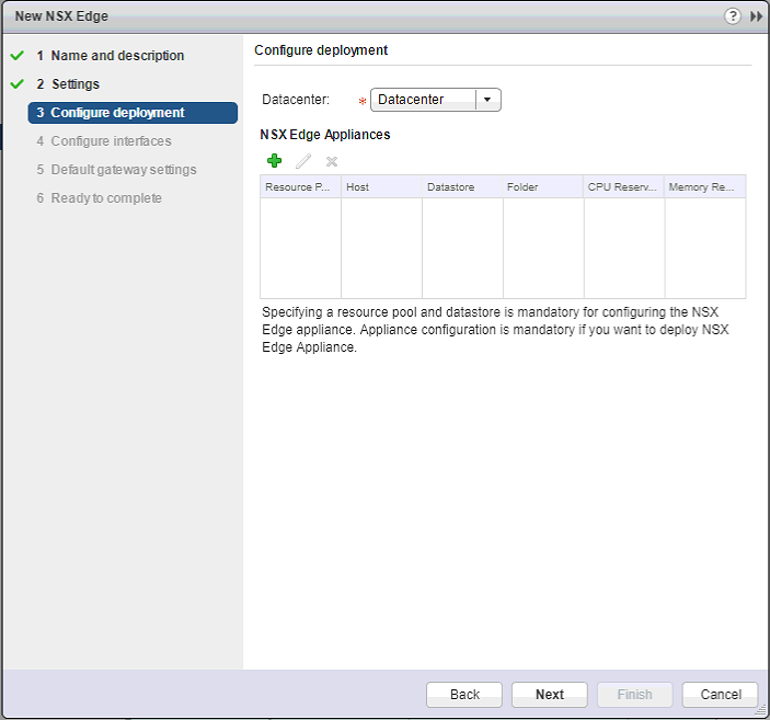
Select the placement parameters. Click OK.
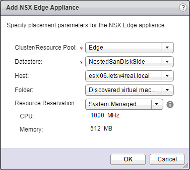
Click Next.

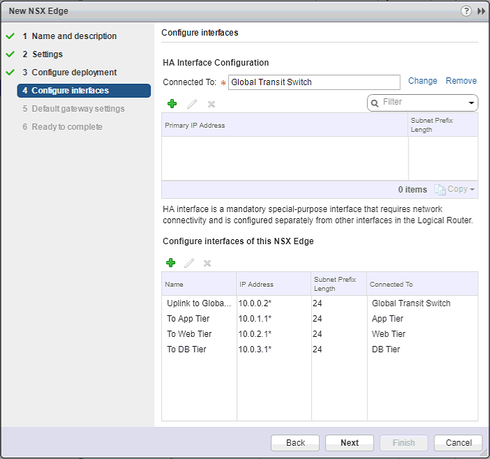
Click the green + to begin creating a interface on the DLR. Select whether this will be a Internal or Uplink interface. In my case I am creating my uplink interface to my transit switch that will eventually be used to peer with my ESG. Assign a IP address also. Click OK.

For the HA configuration, it is recommended that you choose a logical switch to connect to. If you don’t assign a IP address to the HA interface, NSX will generate a IP for you. Create any additional interfaces that you want on the DLR. Click Next.
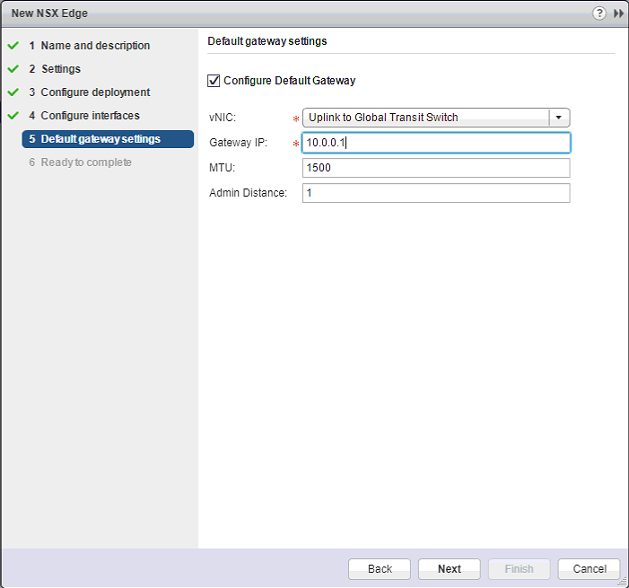
Configure your default gateway. Click Next.
Verify your configuration. Click Finish and the DLR will then be deployed.

Deploy a NSX Edge Services Gateway
Deploying a ESG is very similar to that of a DLR. The ESG will have some slightly different options to chose from.
To begin navigate to Networking & Security > NSX Edges and click the green +. Select Edge Services Gateway. Enter a name for the appliance. Click Next.
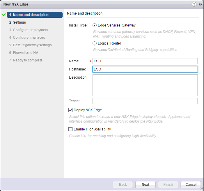
Enter a admin password. It has the same password requirements as the DLR. Once again, Enable SSH is off by default. Enable auto rule generation is enabled by default. This allows control traffic to flow freely on the NSX Edge. It does not auto generate rules for data traffic however. Click Next.

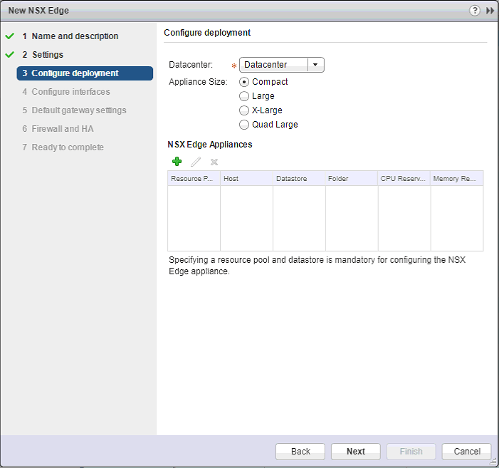
This is one of the options that is not avaliable when deploying a DLR. The size affects the amount of vCPU and RAM that the edge appliance will have. Click Next.
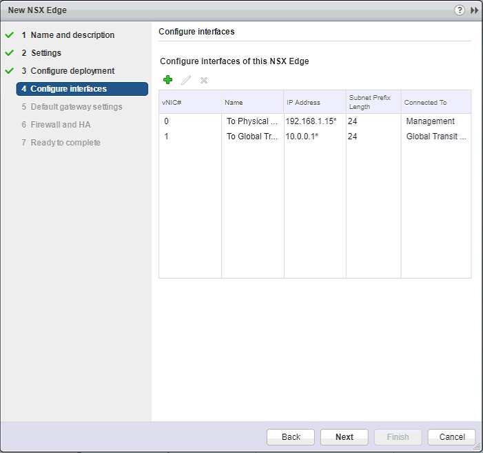
Click the green + to create your interfaces

Decide whether the interface will be a Uplink or Internal interface, connect it to the proper port group or logical switch and assign it a IP address. Optionally, you can enter the MAC address for the interface. The Proxy ARP setting allows the ESG the answer ARP requested intended for other machines. The Send ICMP Redirect option will convey routing information to hosts. Reverse Path Filter verifies the reachability of the source address in packets being forwarded. In enabled mode, the packet must be received on the interface that the router would use to forward the return packet. In loose mode, the source address must appear in the routing table. Click OK.

Create any other interfaces that you need to have in place. Click Next.
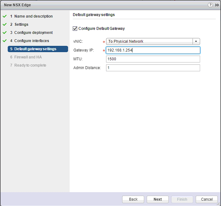
Enter the default gateway IP. Click Next.
Configure the firewall default policy. If you do not configure this option, the default behavior is to deny all traffic. Click Next.
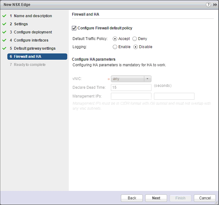
Click Finished and the ESG will deploy.

Configure default gateway parameters
This is something that we configured on deployment but if we ever need to change the settings of the default gateway, navigate to Networking & Security > NSX Edges and double click the edge device. Under Manage > Global Configuration you will see the default gateway settings. Click Edit.
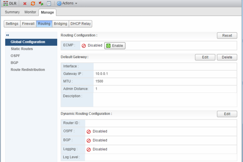
Select the Interface for the default gateway and enter the gateway IP. Click OK.
Publish the Changes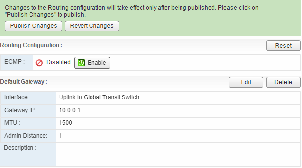
Configure static routes
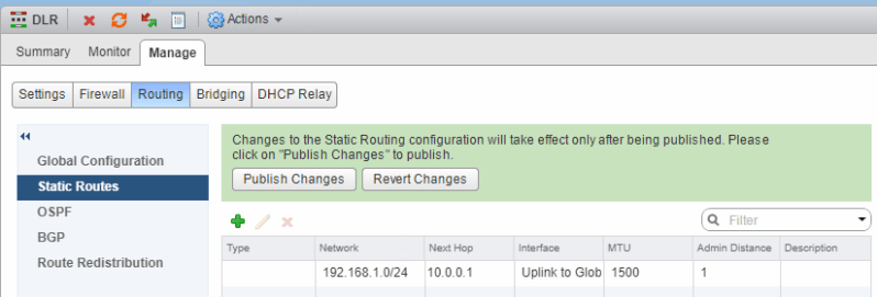
Navigate to Networking & Security > NSX Edges and double click the edge device. Under Manage > Routing > Static Routes click the green +
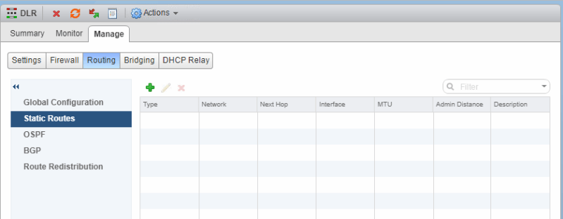
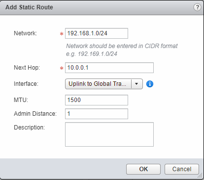
Enter in the network, next hop, and interface information. Click OK.
Publish Changes
Select and configure appropriate dynamic routing protocol according to a deployment plan:
OSPF
For a logical router:
In order to configure OSPF, you must first have a router ID configured.
Navigate to Networking & Security > NSX Edges and double click the edge device. Under Manage > Routing > Global Configuration > Dynamic Routing Configuration click Edit.
By default, it chooses the DLR’s uplink interface as the Router ID. Click OK.

After you publish the changes, navigate to the Manage tab and click OSPF. Click Edit.

Check Enable OSPF. Enter in a Protocol address and Forwarding address that are on the same subnet. The Protocol address is what the DLR uses to create the peering with the adjacent device. In our case, it will be the ESG. The forwarding address is what is used to forward datapath packets. Click OK.

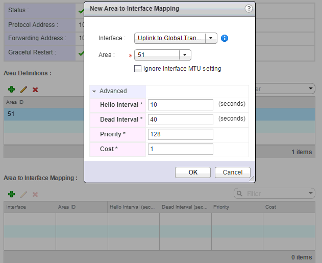
By default, area 51 is created as a NSSA under Area Definitions. I just edited that and made it a Normal area. You can delete it and create whatever area number that you want. Click OK.

Under Area to Interface Mappings, select the interface that you want to be a part of the areas that you create. In this case I am making my uplink interface a part of area 51 to peer with my ESG. Click OK and publish your changes.
For NSX Edge Services Gateway:
The process is done the same ESG with the exception that you don’t need a protocol address. So I’ve given the ESG a router ID and enabled OSPF. The ESG does have another option that can be selected with enabling OSPF and that is Default Originate. Default originate allows the ESG to advertise itself as a default gateway to its neighbors

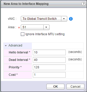
Also with the ESG instead of choosing my uplink interface to map to area 51, I chose my internal interface. This will allow the OSPF peering to take place between the DLR and ESG. Click OK and publish your changes.
BGP
For Logical Router:
In order to configure BGP, you must first have a router ID configured.
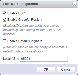
Navigate to Networking & Security > NSX Edges and double click the edge device. Under Manage > Routing > BGP click edit beside BGP Configuration. Check Enable BGP and enter in your AS number

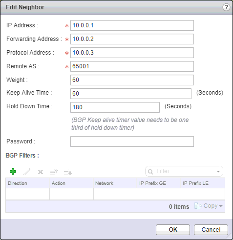
Under Neighbors click the green +. Enter in the IP of the ESG. This is the interface that is pointing toward the DLR, the internal interface. Enter in the forwarding address and protocol address. Once again, the protocol address is what is used to peer with the ESG and the forwarding address is used to forward data packets. So when we go to our ESG to do the neighbor configuration, we will use the DLR’s protocol address and the neighbor IP address. Click OK. Publish changes.
For NSX Edge Services Gateway:
Just like on the DLR, we enable BGP and enter in a Local AS number. The same is true here of the Enable Default Originate as it was with OSPF. The ESG can advertise itself as a default gateway if this is enabled. Click OK.
Click the green + under Neighbors. Enter in the protocol address of the DLR and the remote AS. Click OK. Publish Changes.

Configure route redistribution to support a multi-protocol environment
By default, routers share routes with other routers running the same protocol. In a multi-protocol environment, you must configure route redistribution for cross-protocol route sharing.
Navigate to you edge device and under Manage > Routing > Route Redistribution, click Edit. Select the protocol that you want to enable redistribution for. Click OK.

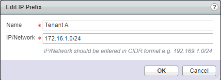
Under IP Prefixes, you can enter in the networks that you want advertise or restrict from being advertised. You reference these IP prefixes in your route redistribution table and BGP filters. Click the green + and add a network. Click OK.
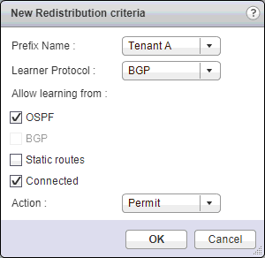
Under Route Redistribution table click the green +. Here is where we will either permit or deny one of our prefix lists from getting advertised. Under Prefix Name, we can select from a list of IP prefixes that we created. The Learner Protocol option is the protocol that is to learn route from other protocols. Allow learning from is where we select the protocols from which routes should be learned. In this case that means, allow BGP to learn routes from OSPF and connected routes. And notice that the action is set to Permit. That can be changed to Deny to remove routes from being advertised. Click OK and publish changes
Note: I did not go over IS-IS configuration because it has been depreciated as of version 6.3.0. I am running 6.3.3 in my lab.
